Exercise 21 - Connecting a LED RGB
1. INTRODUCTION
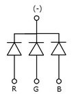
RGB LEDs are composed by one red, one green and one blue. It is important to
know that you can control each one independently.


2. HOW TO CONNECT?
Materials:
· Arduino UNO board
· Protoboard
· Some wire Jumpers
· LED RGB
· 3x 220 ohms resistors (If you do not have LED RGB module)
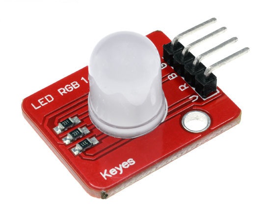
Connecting a RGB LED is very similar to connect a common LED. In this exercise, the LED has common anode. Therefore, you must connect common terminal to 5V on Arduino board. To connect this example a RGB LED module has been used, if you are going to use ordinary RGB LED you must connect 220 ohms resistor to the terminals, in the module this resistors are inside. If you can control the LED colours with Arduino, you should to connect colours terminal with digital pins On Arduino board.

|
EXERCISE_A (Colour sequence) |
EXERCISE_B (Pot adjusting) |
|
|
|
3. PROGRAMMING
EXERCISE_A (Colour sequence)
This program tests LED RGB module, you can modify the code to change the colour of LED. This module has common anode
int red=9;
int blue=6;
int green=3;
int pot1=A0;
int pot2=A1;
int pot3=A2;
void setup(){
pinMode(red,OUTPUT);
pinMode(blue,OUTPUT);
pinMode(green,OUTPUT);
pinMode(pot1,INPUT);
pinMode(pot2,INPUT);
pinMode(pot3,INPUT);
}
When state is LOW, the colour turns on because this module is common Anode. This means that, drop voltage is created when one of anodes is in LOW state.
void loop(){
int value1=analogRead(pot1);
int value2=analogRead(pot2);
int value3=analogRead(pot3);
value1=map(value1,0,1023,0,255);
value2=map(value2,0,1023,0,255);
value3=map(value3,0,1023,0,255);
analogWrite(blue,value1);
analogWrite(green,value2);
analogWrite(red,value3);
}
EXERCISE_B (Pot adjusting)
This program tests LED RGB module, you can modify the potentiometers to change the colour of LED. This module has common anode.
First, pins of potentiometers and the cathodes of RGB led are declared on the sketch, which are set as OUTPUTS and INPUTS in the setup.
int red=9;
int blue=6;
int green=3;
int pot1=A0;
int pot2=A1;
int pot3=A2;
void setup(){
pinMode(red,OUTPUT);
pinMode(blue,OUTPUT);
pinMode(green,OUTPUT);
pinMode(pot1,INPUT);
pinMode(pot2,INPUT);
pinMode(pot3,INPUT);
}
On loop, the value of the potentiometers is read and written on LED OUTPUTs.
void loop(){
int value1=analogRead(pot1);
int value2=analogRead(pot2);
int value3=analogRead(pot3);
value1=map(value1,0,1023,0,255);
value2=map(value2,0,1023,0,255);
value3=map(value3,0,1023,0,255);
analogWrite(blue,value1);
analogWrite(green,value2);
analogWrite(red,value3);
}


