Exercise 1 - Connecting a LED
1. INTRODUCTION
A light-emitting diode (LED) is a two-lead semiconductor light source.

Differentiating terminals:
· The anode is the largest terminal.
· Cathode has a flat edge in terminal base.
· Inside the LED Anode is smaller than cathode.
The voltage necessary to turn on a LED depends of colour.
· Red = 1,8 a 2,2 volts.
· Orange = 2,1 a 2,2 volts.
· Yellow = 2,1 a 2,4 volts.
· Green = 2 a 3,5 volts.
· Blue = 3,5 a 3,8 volts.
· White = 3,6 volts.
(Approximate values)
2. HOW TO CONNECT?
Materials:
· Arduino UNO board
· Protoboard
· Some wire Jumpers
· LED
· 220 ohms resistors
LED anode always goes connected to the positive.
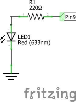
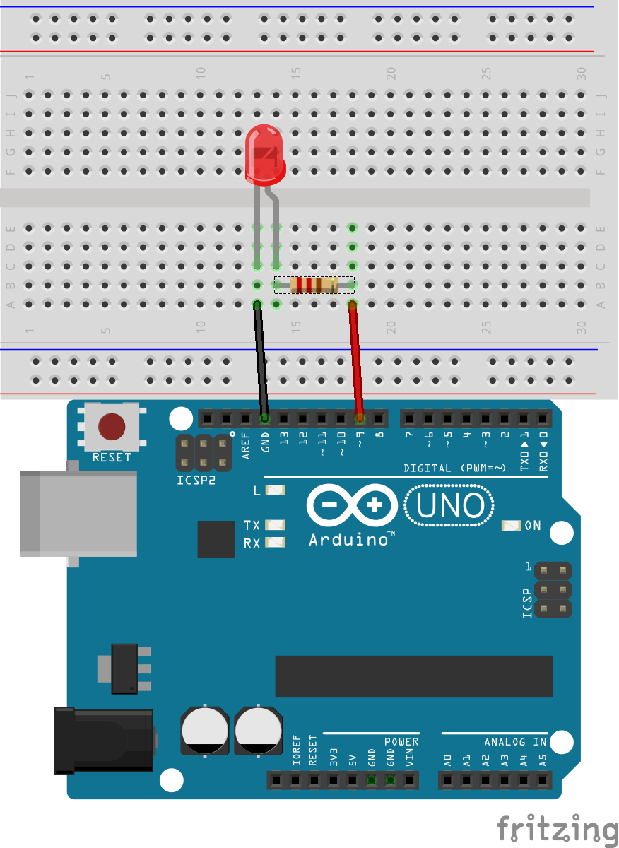
To use a LED as actuator component, we can connect it in Arduino board output. On EXERCISE_B you have to connect the LED to a PWM pin, for example pin9, but pins: 11, 10, 6, 5, 3 also have PWM function.
PWM
Pulse-width modulation. When you have a continuous current you can convert it to a pulsing wave, which can be switched its pulse width. If you change the pulse width you are changing the RMS value (Root Mean Square value)
WARNING:
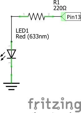
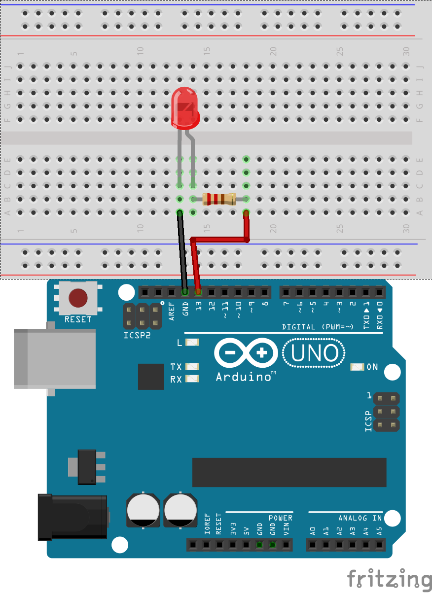
In EXERCISE_A, you can use internal led, which is connected to pin 13 because it have an internal resistor. To connect external LED to pin 13 or another pin, you should put a 220 ohms resistor.
|
EXERCISE_A (Blink)
|
EXERCISE_B (Fade)
|
3. PROGRAMMING
EXERCISE_A (Blink)
-In the first part of the program, led Pin is associated with an Arduino board pin (number 13). In the setup these pin is declared as output with pinMode() function.
int led=13;//Assign the name led to pin 13
void setup(){
pinMode(led,OUTPUT);//Set led pin output
}
-In the second part, we will write HIGH and LOW level in led with digitalWrite() function. HIGH level puts 5V in pin and LOW level puts 0V.
This programs change between HIGH and LOW level in led. When puts HIGH level the program waits 500 milliseconds and then puts LOW level and wait 500 milliseconds another time. This action is repeated infinitely.
void loop(){
digitalWrite(led,HIGH);//Write HIGH voltage level in led pin
delay(500);//Stop program 500 milliseconds
digitalWrite(led,LOW);//Write LOW voltage level in led pin
delay(500);
}
EXERCISE_B(Fade)
This exercise is similar to EXERCISE_A, but now LED is turned on and off with a gradient of luminosity.
First, LED is associated with an Arduino pin. Furthermore, the gradient is controlled by an integer variable “i”.
int led=9;//Assigns led to a pin with PWM function
int i=0;
void setup(){
pinMode(led,OUTPUT);
}
To simulate the gradient, we can use a for loop which can increments our variable “i” one by one until “i” equals maximum or minimum value.
We can put values between 0-255 in analog outputs, thus first for loop must work between these values. It increments “i” one by one until “i” equals 255. These value are written on led pin, then the program waits 5 milliseconds.
void loop(){
//for increments i, one on one
for(i=0;i<=255;i++){
analogWrite(led,i);
delay(5);
}
The same in the second for loop, but in this case “i” decrements its value one by one until it equals 0.
//for decrements i , one on one
for(i=255;i>=0;i--){
analogWrite(led,i);
delay(5);
}
}


